Building a resilient network on AWS starts with the fundamental security layers of Amazon VPC. While tools like Security Groups and Network ACLs are indispensable for basic traffic filtering, they are often insufficient for modern compliance standards. To truly secure high-value workloads, teams need more than just port-based rules; they require Deep Packet Inspection (DPI), application protocol detection, and the ability to enforce strict domain-based filtering.
For these advanced requirements, we use AWS Network Firewall, a stateful, managed service designed for scale and high-performance security. While basic implementations are straightforward, this post focuses on the Distributed Deployment Model. We will walk through how to integrate an Application Load Balancer (ALB) with firewall endpoints in every Availability Zone (AZ) to ensure all traffic is inspected while eliminating cross-AZ data transfer costs.
Using Terraform, we’ll demonstrate how to automate the complex "routing magic" required to place the firewall directly into the traffic path of your private web servers, providing a robust template for defense-in-depth.
Where AWS Network Firewall Operates & Why It's Different
Every AWS network security control construct, operates at a specific layer and position in the traffic path. Understanding where NFW sits in the traffic path tells you exactly why you need it alongside Security Groups, NACLs, and WAF
.png)
Security Groups answer: "Can this IP talk to this port?" They are allow-lists at the ENI level. They can't detect a C2 callback on port 443 from a compromised instance, or DNS tunneling through an allowed resolver.
NACLs are stateless packet filters at the subnet boundary. They operate on 5-tuples (source/dest IP, port, protocol) with no session awareness every packet is evaluated independently.
WAF inspects HTTP/HTTPS traffic at the ALB or CloudFront. It excels at SQLi, XSS, and OWASP Top 10 protection, but has zero visibility into non-HTTP protocols: SMTP exfiltration, SSH brute-force, or lateral movement over custom ports.
The NFW is a stateful inspection engine that sees every packet, not just HTTP. It can match domain names, TLS metadata, protocol signatures, and threat intelligence; things the other tools miss. It sits in the traffic path as a transparent bump-in-the-wire.
Deployment Models
AWS Network Firewall supports several deployment architectures:
- Centralized — a single inspection VPC with NFW, connected to workload VPCs via Transit Gateway.
- Distributed — NFW deployed directly inside each workload VPC.
- Combined — centralized for east-west (inter-VPC) traffic, distributed for north-south (internet) traffic.
In this article, we focus exclusively on the distributed north-south model. This is the natural fit when each VPC has its own ALBs serving workloads and a Regional NAT Gateway for egress. The firewall lives alongside the workload it protects, with one endpoint per Availability Zone.
The Baseline
Before adding any firewall, let's establish the architecture that most production workloads on AWS already use. This is the starting point, the "before" picture.
A standard 2-AZ web application with:
- An Application Load Balancer receiving internet traffic
- EC2 instances in private subnets serving the application
- A Regional NAT Gateway providing outbound internet access for the private instances across all AZs
- Security Groups and NACLs enforcing access control
The Architecture
.png)
Component Roles
VPC and Subnets
The VPC uses a /16 CIDR (e.g., 10.0.0.0/16) with two tiers of subnets across two AZs:
- Public subnets (
10.0.1.0/24,10.0.2.0/24) — host ALB ENIs and NAT Gateways. These subnets have a route to the Internet Gateway. - Private subnets (
10.0.10.0/24,10.0.20.0/24) — host EC2 web servers. No direct internet access; egress flows through the Regional NAT Gateway.
Internet Gateway and ALB
The Internet Gateway (IGW) is attached to the VPC. The ALB is deployed across both public subnets, listening for HTTP/HTTPS traffic and distributing it to EC2 targets in the private subnets.
- The public subnets can share one route table because they all route to the same IGW.
- Each private subnet has its own route table that directs traffic to the NAT Gateway endpoint in the same AZ
Regional NAT Gateway
A single Regional NAT Gateway serves all AZs, with one Elastic IP per AZ. Each private subnet's route table sends 0.0.0.0/0 to the regional gateway. AWS handles AZ-aware routing automatically, using the EIP assigned to each AZ for outbound traffic. This gives instances outbound internet access (for package updates, API calls, etc.) without exposing them to inbound traffic.
Network ACLs
NACLs provide a stateless safety net at the subnet boundary. In a default configuration, both public and private subnet NACLs allow all traffic; they serve as a backstop if Security Groups are misconfigured. Some teams tighten NACLs to block specific IP ranges or restrict ephemeral port ranges. We will use the default rules.
Security Groups
Security Groups provide the last-mile access control:
- ALB Security Group — allows inbound HTTP/HTTPS from
0.0.0.0/0, and allows all outbound. - EC2 Security Group — allows inbound HTTP only from the ALB Security Group, and allows all outbound.
This is the standard pattern: the ALB faces the internet, the EC2 instances only accept traffic from the ALB. This is called Security Group chaining.
What's Missing?
This architecture has access control (Security Groups, NACLs) and HTTP inspection (WAF on the ALB), but it has no behavioral inspection of network flows. There is nothing between the IGW and the ALB that can:
- Detect a compromised instance calling a Command and Control (C2) server on port 443.
- Block outbound traffic to known malware domains.
- Alert on DNS tunneling or protocol anomalies.
- Inspect non-HTTP protocols at all
- Enforce egress domain allowlists
This is where NFW comes in.
Adding AWS Network Firewall: What Changes
Adding NFW to this architecture introduces three structural changes:
- New firewall subnets — a dedicated
/28subnet per AZ for NFW endpoints - The NFW resource itself — firewall, policy, and rule groups
- Route table restructure — from 2 route tables to 4 tiers, inserting NFW into both inbound and outbound paths
Let's walk through each change.
The Protected Architecture
.png)
AWS Network Firewall endpoint is deployed into a dedicated subnet of a VPC. We call this subnet an AWS Network Firewall subnet or simply firewall subnet. Depending on the use case and deployment model, the firewall subnet could be either public or private. For high availability (HA) and Multi-AZ deployments, allocate a subnet per Availability Zone (AZ)
Change 1: Firewall Subnets
Firewall subnets are subnets which are dedicated for the AWS NFW endpoints to be deployed. For our two-AZ HA scenario, we have one Firewall subnet per AZ. The NFW endpoints consume IP addresses from subnets which are /28 blocks providing (16 IPs, 11 usable) which is sufficient as these subnets exist solely for the firewall and must not host any other resources.
According to the AWS Network Firewall Developer Guide:
💡 Reserve these firewall subnets for the exclusive use of Network Firewall. A firewall endpoint can't filter traffic coming into or going out of the subnet in which it resides, so don't place other applications in the firewall endpoint subnets..png)
Change 2: The Network Firewall Resources and Components
The firewall itself is composed of four resources that work as one:
Stateless Rule Group
The stateless engine is the first pass which is high-speed, per-packet filtering. A clean default is to forward everything to the stateful engine for deep inspection:
resource "aws_networkfirewall_rule_group" "stateless" {
  name     = "${var.project_name}-stateless-rg"
  type     = "STATELESS"
  capacity = 50

  rule_group {
    rules_source {
      stateless_rules_and_custom_actions {
        stateless_rule {
          priority = 10
          rule_definition {
            match_attributes {
              source      { address_definition = "0.0.0.0/0" }
              destination { address_definition = "0.0.0.0/0" }
            }
            actions = ["aws:forward_to_sfe"]
          }
        }
      }
    }
  }
}
This rule matches all traffic (0.0.0.0/0 → 0.0.0.0/0) and forwards it to the stateful engine (aws:forward_to_sfe). In production, you'd add stateless rules to block known-bad IPs before they hit the stateful engine (which is slower and costlier)
Stateful Rule Group
The stateful engine is where the real inspection happens. It uses Suricata-compatible rules that can match on protocols, ports, domains, TLS metadata, and more:
resource "aws_networkfirewall_rule_group" "stateful" {
  name     = "${var.project_name}-stateful-rg"
  type     = "STATEFUL"
  capacity = 100

  rule_group {
    rules_source {
      rules_string = <<-RULES
        pass tcp any any -> any 80 (msg:"Allow HTTP"; sid:100001; rev:1;)
        pass tcp any any -> any 443 (msg:"Allow HTTPS"; sid:100002; rev:1;)
        pass icmp any any -> any any (msg:"Allow ICMP"; sid:100003; rev:1;)
        pass tcp any 80 -> any any (msg:"Allow HTTP response"; sid:100004; rev:1;)
        pass tcp any 443 -> any any (msg:"Allow HTTPS response"; sid:100005; rev:1;)
      RULES
    }
  }
}This demo allows HTTP, HTTPS, and ICMP. A production deployment would use:
- AWS Managed Threat Intelligence rule groups for known-bad indicators
- Domain-based allow lists using TLS SNI inspection (
tls.sni; content:".amazonaws.com"; endswith;) - Community Suricata rulesets (Emerging Threats Open ruleset, Proofpoint ET Pro)
Important: The capacity value is immutable after creation. If you set it to 100 and later need 150 rules, you must recreate the rule group. Over-provision from the start.
Firewall Policy
The policy wires the two engines together. Stateless first, then stateful:
resource "aws_networkfirewall_firewall_policy" "main" {
  name = "${var.project_name}-policy"

  firewall_policy {
    stateless_default_actions          = ["aws:forward_to_sfe"]
    stateless_fragment_default_actions = ["aws:forward_to_sfe"]

    stateless_rule_group_reference {
      resource_arn = aws_networkfirewall_rule_group.stateless.arn
      priority     = 100
    }

    stateful_rule_group_reference {
      resource_arn = aws_networkfirewall_rule_group.stateful.arn
    }
  }
}The packet processing pipeline looks like this:
- Packet arrives at the NFW endpoint.
- Stateless Engine - It matches the match all rule which forwards to the stateful engine
match all -> forward_to_sfe - Stateful Engine - The packet is evaluated against Suricata rules which will
pass / drop / alert / reject
Change 3: Route Table Restructure: From 2 Tiers to 4
This is the most significant change. The baseline architecture has 2 route tables (public + private). Adding NFW requires 4 distinct tiers to insert the firewall on both inbound and outbound paths:
- Before, in the Public Route Tables,
0.0.0.0/0 -> IGWand in the Private Route Tables,0.0.0.0/0 -> RNAT GW - Now, in the Public Route Tables,
0.0.0.0/0 -> NFW Endpoint - The Private Route Tables remain unchanged,
0.0.0.0/0 -> RNAT GW… - The NAT GW’s Route table has
0.0.0.0/0 -> NFW Endpoint - The Firewall Route Table,
0.0.0.0/0 -> IGW - VPC Ingress routing is enabled via the IGW Edge Route Table which directs incoming traffic to the NFW Endpoints per AZ.
The high-level route table layout:
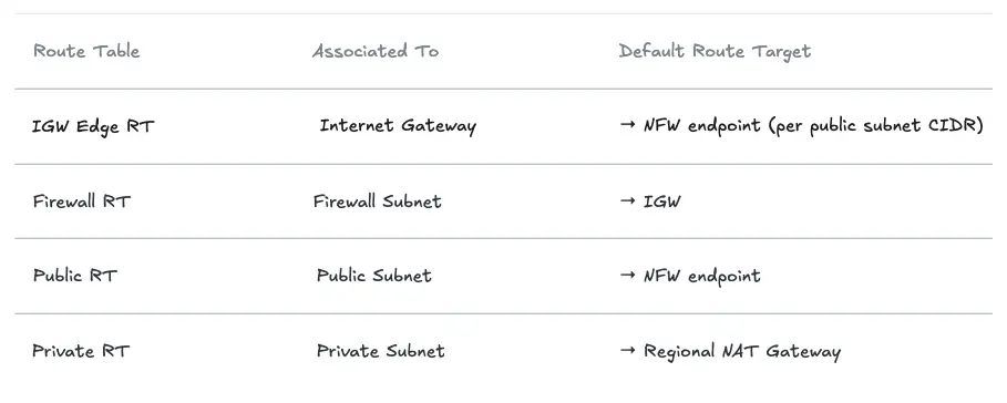
Note that there are separate route tables per AZ for the Firewall, Public and Private Route Tables.
Let's look at each route table and why it exists.
The IGW Edge Route Table (The Non-Obvious Part)
This route table is associated with the gateway itself, not a subnet, using gateway_id. This is what intercepts inbound traffic before it reaches the public subnets and redirects it through NFW:
# One route per public subnet CIDR → NFW endpoint in that subnet's AZ
resource "aws_route" "igw_to_nfw" {
  count = length(var.availability_zones)

  route_table_id         = aws_route_table.igw_edge.id
  destination_cidr_block = var.public_subnet_cidrs[count.index]
  vpc_endpoint_id        = local.firewall_endpoint_ids[var.availability_zones[count.index]]
}

# Associate the route table with the IGW (not a subnet!)
resource "aws_route_table_association" "igw_edge" {
  gateway_id     = aws_internet_gateway.main.id
  route_table_id = aws_route_table.igw_edge.id
}Without this, inbound traffic from the internet would land directly in the public subnet which will bypass the firewall entirely. This is also known as VPC Ingress Routing.
The Firewall Route Table
After NFW inspects a packet, it needs an exit path. The firewall subnet's route table simply points to the IGW:
resource "aws_route" "firewall_to_igw" {
  count = length(var.availability_zones)

  route_table_id         = aws_route_table.firewall[count.index].id
  destination_cidr_block = "0.0.0.0/0"
  gateway_id             = aws_internet_gateway.main.id
}
The Public Route Table (Changed!)
This is the critical change from the baseline. Previously, public subnets routed 0.0.0.0/0 directly to the IGW. Now they route through NFW; this is what captures outbound traffic from the Regional NAT Gateway for egress inspection:
resource "aws_route" "public_to_nfw" {
  count = length(var.availability_zones)

  route_table_id         = aws_route_table.public[count.index].id
  destination_cidr_block = "0.0.0.0/0"
  vpc_endpoint_id        = local.firewall_endpoint_ids[var.availability_zones[count.index]]
}
💡 Critical: Public subnets can no longer share a single route table. Each AZ needs its own public route table pointing to the NFW endpoint in that same AZ. NFW does not support cross-AZ routing — a packet from AZ-a routed to an NFW endpoint in AZ-b will be dropped.The Private Route Table (Unchanged)
Private subnets still route 0.0.0.0/0 to the Regional NAT Gateway. No change here, the NAT Gateway naturally feeds into the public subnet's route table, which now points to NFW.
Tracing the Traffic Flows
Now that NFW is wired in, let's trace both directions end-to-end.
Inbound: Internet → Web Server
Every inbound packet is inspected by NFW before it reaches the ALB. The firewall can block known-bad source IPs, detect protocol anomalies, and alert on suspicious patterns all before WAF or Security Groups are evaluated.
.png)
- A Client from the internet initiates a connection to the public IP of the ALB which lands on the IGW
- The traffic is routed to the NFW for the AZ in accordance with the IGW Ingress Routing Table
- If the traffic passes the NFW inspection it is forwarded to the ALB in accordance with the Firewall Subnet Route Table.
- The ALB in the public subnet forwards the traffic to the target group according to the public subnet’s Route table and listener rules.
- Response traffic is returned back to the ALB in accordance with the Private Subnet Route Table.
- In accordance with the Public Route Table the ALB forwards the traffic to the NFW endpoint in the same AZ.
- If the traffic is compliant, the NFW forwards the traffic to the IGW
- The IGW forwards the traffic back to the internet towards the client.
Outbound: Web Server → Internet
All outbound traffic from private subnets passes through NFW regardless of destination port, protocol, or application. This is where you enforce egress domain allowlists, block C2 infrastructure, and alert on unusual protocol usage.
.png)
- The instance initiates traffic towards the internet which will be routed to the NAT GW in accordance with the Private Subnet’s Route Table.
- The source IP of the packet is swapped with the public IP address of the NAT GW and forwarded to the Firewall Subnet in accordance with the Public Route Table.
- The traffic is inspected by the NFW for inspection. If it complies with the rules, it is forwarded to the IGW
- The IGW forwards the traffic to the Internet.
ALB and NAT Gateway Integration Nuances
The ALB as a Client
From NFW's perspective, the ALB is a client, not a passthrough. The ALB terminates TCP connections and opens new ones to backend targets. This means:
- NFW sees the ALB's private IP as the source when traffic flows from ALB to EC2, not the original client IP. Internet-facing threat rules operate on the inbound path (IGW → NFW → ALB), not the backend path.
- Return traffic from the ALB flows through the public subnet route table, which now points to NFW. The stateful engine tracks connection state, so the
passrule for TCP 80/443 allows return traffic automatically.
Layer your controls accordingly:
- NFW rules → inspect source IPs from the internet (pre-ALB, inbound path)
- WAF rules: → inspect HTTP headers/body at ALB (post-NFW, pre-backend)
- Security Group rules → enforce ALB-only access to EC2 (post-ALB, per-ENI)
TLS Inspection
By default, NFW cannot inspect the encrypted content inside HTTPS sessions, only the SNI at handshake time. The NFW supports TLS Inspection which is practical in environments requiring DLP (data loss prevention), payload-based IDS signatures, or regulatory compliance mandating full traffic inspection (PCI-DSS, HIPAA).
However, there are some trade-offs to weigh before enabling TLS inspection:
- Decryption and re-encryption adds latency
- Clients that pin the ALB’s public certificate will reject the NFW’s certificate and fail TLS handshake
Consider using AWS WAF for HTTP/HTTPS inspection instead.
Egress Inspection via Regional NAT Gateway
The routing chain Private Subnet → Regional NAT GW → Public RT → NFW → IGW means all outbound traffic is inspected regardless of protocol. This is the position to enforce:
- Egress domain allowlists (only approved destinations)
- DNS resolver restrictions (block DNS tunneling)
- Outbound protocol restrictions (block non-standard protocols)
💡 NFW can operate in IDS mode (alert-only, and doesn’t drop any packets). This is critical for understanding your traffic baseline before writing deny rules.Operational Caveats
- You cannot use the VPC's main route table for public subnets with NFW. The edge routing and per-AZ endpoint references require explicit, dedicated route tables for every subnet tier.
- Each AZ must reference its own NFW endpoint. Cross-AZ routing to an NFW endpoint will cause packet drops.
- Stateful rule group
capacityis immutable after creation. Over-provision generously. - If an NFW endpoint in one AZ becomes unhealthy, NFW may re-route to a healthy endpoint temporarily violating in-AZ routing. Monitor
FirewallEndpointHealthCloudWatch metrics. - NFW provisioning takes 7–15 minutes. Don't assume it's as fast as other AWS resources in CI/CD pipelines.
- In
DEFAULT_ACTION_ORDERmode, unmatched traffic is passed, not dropped. For deny-by-default, use Strict Order evaluation or add an explicit catch-alldroprule. - FLOW logs emit one record per connection (not per packet), but high-throughput environments can generate significant CloudWatch volume. Consider short retention (7–14 days), routing FLOW logs to S3, and keeping only ALERT logs in CloudWatch for real-time monitoring.
Summary
With NFW, you're no longer just controlling who talks to what. You're also watching what they actually do. The distributed pattern, one NFW endpoint per AZ, wired through a four-tier route table hierarchy is the natural fit for workloads where each VPC has its own ALBs and a Regional NAT Gateway. It avoids cross-AZ traffic costs, survives single-AZ failure, and gives every subnet tier clean inspection semantics.
When Security Groups tell you who can talk to what, WAF tells you what they're sending over HTTP/HTTPS, and NFW tells you what every flow is doing (DPI). Together they form a defense-in-depth posture that's considerably harder to bypass than any single layer alone.
References
https://aws.amazon.com/network-firewall/
https://docs.aws.amazon.com/network-firewall/latest/developerguide/arch-igw-ngw.html
https://aws.amazon.com/blogs/aws/aws-network-firewall-new-managed-firewall-service-in-vpc/
https://forum.suricata.io/t/emerging-threats-pro-open-ruleset-for-suricata-7-0-3-now-available/4714


%20(1).svg)

.svg)