In multi-VPC AWS environments, each VPC often gets its own Internet Gateway (IGW) or NAT Gateway (NATGW) for outbound internet access. This could lead to higher operational overhead, and increased costs from multiple NAT Gateways. Moreover, security becomes fragmented with multiple entry/exit points to monitor.
Centralized internet egress solves these problems by funneling all outbound internet traffic through a single, well-controlled exit point. This architecture isn't just about cost savings—it's about gaining visibility, control, and security over your organization's internet-bound traffic.
In this post, will examine how this can be achieved with two key enabling AWS services: AWS Transit Gateway and the newly released AWS Regional Gateway as well as some key design trade-offs.
Architecture Overview
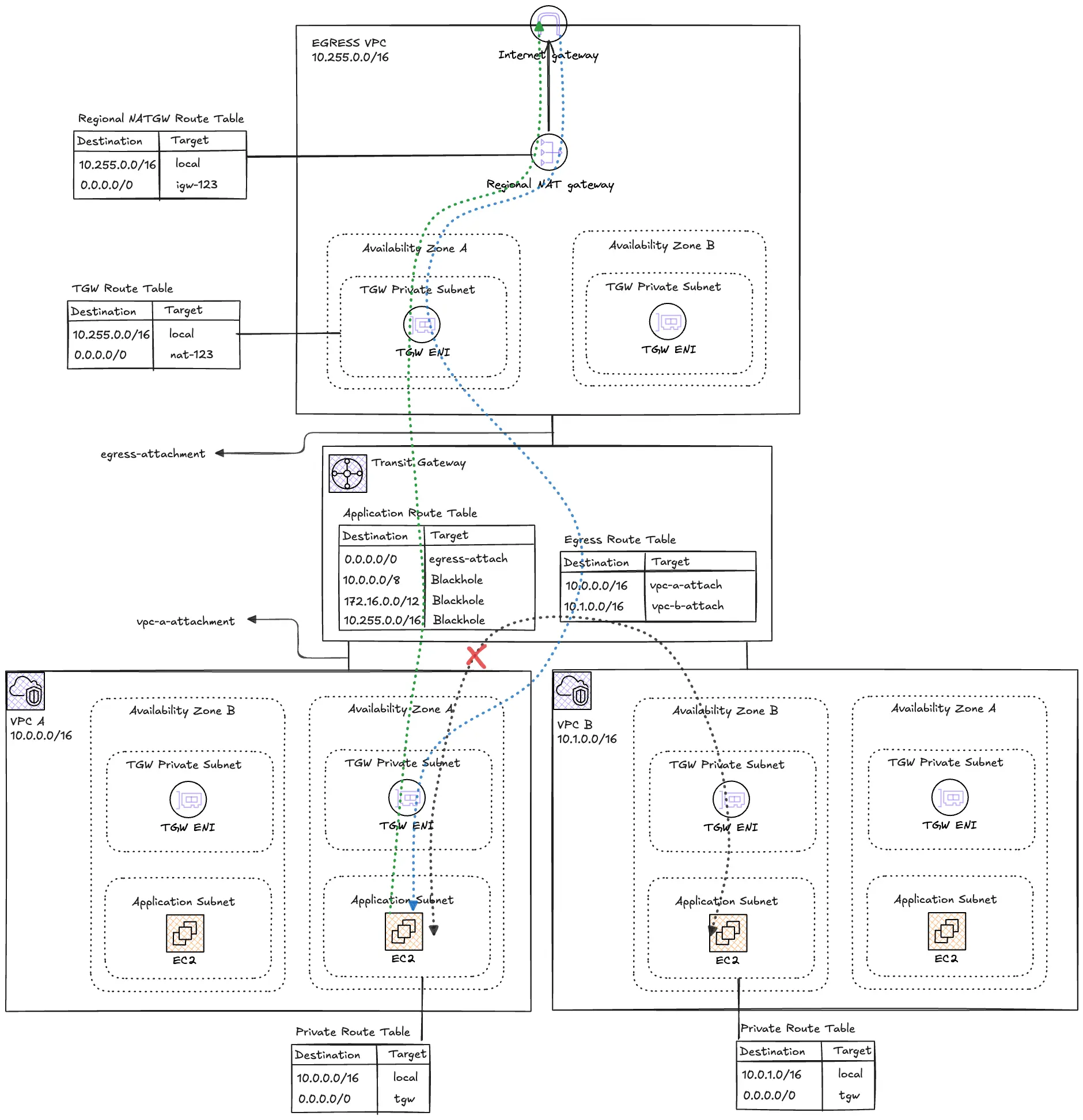
Centralized egress patterns use AWS Transit Gateway as the routing hub connecting multiple spoke VPCs to a dedicated Egress VPC containing a single Regional NAT Gateway.
Key Components
This architecture comprises three critical layers:
Egress VPC - The Internet Gateway
The Egress VPC is a single centralized exit point for all internet-bound traffic in the Region. The main components within this VPC are the Internet Gateway (IGW) and the Regional NAT Gateway (NATGW). The Regional NATGW provides a single construct which spans multiple availability zones eliminating the need to deploy and manage multiple Zonal NATGWs. Due to the deployment model of the Regional NATGW, manually assigning Elastic IPs is not necessary.
From a design perspective, only private subnets are required from the Transit Gateways attachment subnets. This layer is only for infrastructure routing and hosts no workloads.
Transit Gateway (TGW) - The Regional Router
The TGW connects all the spoke VPCs to the Egress VPC via attachments and enforces routing policies. All outbound internet traffic from spoke VPCs will be routed to the Egress VPC and vice-versa for the inbound return traffic.
The default route table and default propagation will be disabled in favor of explicit control via two custom route tables:
- Application Route Table: To be used by Spoke VPCs with blackhole routes to prevent cross-VPC communication
- Egress Route Table: For the Egress VPC to route traffic back to the specific spoke VPCs
RFC 1918 prefixes will also be blackholed to prevent lateral movements between spokes.
Client VPCs - Workload VPCs
These VPCs host private application workloads with controlled internet access. The VPCs are completely isolated from each other. Since no direct internet access is allowed on this VPCs, they will only host private subnets for the workloads and also for the TGW attachments.
No IGWs, public subnets or Zonal NATGWs are permitted in these VPCs
Routing Path
Let’s examine what happens when an instance in a spoke VPC wants to download patches from the internet after obtaining the public IP address from DNS resolution.
- Source Subnet (VPC-A): The instance sends the packet with the DNS resolved Public IP as the destination. The subnet's Route Table intercepts the request for which matches the
0.0.0.0/0route entry. Instead of pointing to a local gateway, the route directs this traffic to a Transit Gateway (TGW) attachment. - Transit Gateway: The packet enters the TGW. The TGW consults its own TGW Route Table associated with VPC-A. A static route for the internet (
0.0.0.0/0) directs the packet to the attachment for the Centralized Egress VPC. - Egress VPC Entrance: The packet arrives in the Egress VPC. It lands in a "Transit Subnet" where the Subnet Route Table is configured to send all outbound traffic to a NAT Gateway. (
0.0.0.0/0 → nat-1234) - Network Address Translation: The Regional NAT Gateway receives the packet, replaces theinstance's private IP with its own Public IP, and prepares it for the public internet.
- Internet Gateway (IGW): The NAT Gateway’ route table directs
0.0.0.0/0to the IGW, which finally routes the packet to the public destination. - The Return Journey: The response follows the same path in reverse. The Regional NATGWuses its internal translation table to ensure the response is sent back through the TGW to the specific instance in VPC-A that started the request.
Key Configurations
In this scenario, we will use two spoke VPCs, VPC_A and VPC_B with EC2 instances requiring internet egress routing to the Egress VPC.
Below are the VPC CIDR ranges for the VPCs.
| VPC Name Tag | IPv4 CIDR |
|---|---|
| egress-vpc | 10.255.0.0/16 |
| vpc-a | 10.0.0.0/16 |
| vpc-b | 10.1.0.0/16 |
The table below shows the mappings of the various subnets and Availability Zones (AZs) in each of the VPCs.
| Subnet Name Tag | VPC | AZ | IPv4 CIDR |
|---|---|---|---|
| egress-pri-tgw-use1a | egress-vpc | us-east-1a | 10.255.3.0/28 |
| egress-pri-tgw-use1b | egress-vpc | us-east-1b | 10.255.3.16/28 |
| vpc-a-pri-use1a | vpc-a | us-east-1a | 10.0.1.0/24 |
| vpc-a-pri-use1b | vpc-a | us-east-1b | 10.0.2.0/24 |
| vpc-a-pri-tgw-use1a | vpc-a | us-east-1a | 10.0.3.0/28 |
| vpc-a-pri-tgw-use1b | vpc-a | us-east-1b | 10.0.3.16/28 |
| vpc-a-pri-use1a | vpc-b | us-east-1a | 10.1.1.0/24 |
| vpc-a-pri-use1b | vpc-b | us-east-1b | 10.1.2.0/24 |
| vpc-a-pri-tgw-use1a | vpc-b | us-east-1a | 10.1.3.0/28 |
| vpc-a-pri-tgw-use1b | vpc-b | us-east-1b | 10.1.3.16/28 |
The table below shows the mappings of the TGW to the Spoke and Egress VPCs;
| Attachment Type | Attachment Name Tag | Subnets Name Tag |
|---|---|---|
| VPC | egress-attachment | egress_tgw_az1 egress_tgw_az2 |
| VPC | vpc-a-attachment | vpc_a_tgw_az1 vpc_a_tgw_az2 |
| VPC | vpc-b-attachment |
vpc_b_tgw_az1 |
Spoke VPC Configurations
The route tables for subnets where resources require internet egress need to route internet traffic to the TGW ENI. Below is a snippet for VPC_A. The depends_on is necessary because the TGW attachment needs to exist first before it can be referenced.
resource "aws_route_table" "vpc_a_pri" {
  vpc_id = aws_vpc.vpc_a.id

  tags = {
    Name = "vpc-a-pri-rt"
  }
}

# Default route to Transit Gateway
resource "aws_route" "vpc_a_pri_tgw" {
  route_table_id         = aws_route_table.vpc_a_pri.id
  destination_cidr_block = "0.0.0.0/0"
  transit_gateway_id     = aws_ec2_transit_gateway.main.id

  depends_on = [aws_ec2_transit_gateway_vpc_attachment.vpc_a]
}

resource "aws_route_table_association" "vpc_a_pri_az1" {
  subnet_id      = aws_subnet.vpc_a_pri_az1.id
  route_table_id = aws_route_table.vpc_a_pri.id
}

resource "aws_route_table_association" "vpc_a_pri_az2" {
  subnet_id      = aws_subnet.vpc_a_pri_az2.id
  route_table_id = aws_route_table.vpc_a_pri.id
}
The TGW subnets in each Spoke VPC also need a route to the TGW. This handles return traffic and ensures the TGW ENIs can communicate properly.
resource "aws_route_table" "vpc_a_tgw" {
  vpc_id = aws_vpc.vpc_a.id

  tags = {
    Name = "vpc-a-tgw-rt"
  }
}

resource "aws_route" "vpc_a_tgw_default" {
  route_table_id         = aws_route_table.vpc_a_tgw.id
  destination_cidr_block = "0.0.0.0/0"
  transit_gateway_id     = aws_ec2_transit_gateway.main.id

  depends_on = [aws_ec2_transit_gateway_vpc_attachment.vpc_a]
}

resource "aws_route_table_association" "vpc_a_tgw_az1" {
  subnet_id      = aws_subnet.vpc_a_tgw_az1.id
  route_table_id = aws_route_table.vpc_a_tgw.id
}

resource "aws_route_table_association" "vpc_a_tgw_az2" {
  subnet_id      = aws_subnet.vpc_a_tgw_az2.id
  route_table_id = aws_route_table.vpc_a_tgw.id
}
TGW Configurations
To guarantee explicit routing control, the DefaultRouteTableAssociation and DefaultRouteTablePropagation will be disabled in favor of the following route tables
resource "aws_ec2_transit_gateway" "main" {
  description                     = "Transit Gateway for centralized egress"
  amazon_side_asn                 = var.tgw_asn
  auto_accept_shared_attachments  = "enable"
  default_route_table_association = "disable" # Critical: Disable for proper isolation
  default_route_table_propagation = "disable" # Critical: Disable for proper isolation
  dns_support                     = "enable"
  vpn_ecmp_support                = "enable"

  tags = {
    Name = "tgw-egress"
  }
}
A TGW Attachment is created for each VPC.
# Egress VPC Attachment
resource "aws_ec2_transit_gateway_vpc_attachment" "egress" {
  transit_gateway_id = aws_ec2_transit_gateway.main.id
  vpc_id             = aws_vpc.egress.id
  subnet_ids = [
    aws_subnet.egress_tgw_az1.id,
    aws_subnet.egress_tgw_az2.id
  ]

  dns_support                                     = "enable"
  transit_gateway_default_route_table_association = false
  transit_gateway_default_route_table_propagation = false

  tags = {
    Name = "egress-attachment"
  }
}

# VPC_A Attachment
resource "aws_ec2_transit_gateway_vpc_attachment" "vpc_a" {
  transit_gateway_id = aws_ec2_transit_gateway.main.id
  vpc_id             = aws_vpc.vpc_a.id
  subnet_ids = [
    aws_subnet.vpc_a_tgw_az1.id,
    aws_subnet.vpc_a_tgw_az2.id
  ]

  dns_support                                     = "enable"
  transit_gateway_default_route_table_association = false
  transit_gateway_default_route_table_propagation = false

  tags = {
    Name = "vpc-a-attachment"
  }
}

# VPC_B Attachment
resource "aws_ec2_transit_gateway_vpc_attachment" "vpc_b" {
  transit_gateway_id = aws_ec2_transit_gateway.main.id
  vpc_id             = aws_vpc.vpc_b.id
  subnet_ids = [
    aws_subnet.vpc_b_tgw_az1.id,
    aws_subnet.vpc_b_tgw_az2.id
  ]

  dns_support                                     = "enable"
  transit_gateway_default_route_table_association = false
  transit_gateway_default_route_table_propagation = false

  tags = {
    Name = "vpc-b-attachment"
  }
}
Custom route tables for the Egress VPC and for all the Spoke VPCs is created and associated with the corresponding TGW attachments.
# Egress Route Table - For egress VPC traffic
resource "aws_ec2_transit_gateway_route_table" "egress" {
  transit_gateway_id = aws_ec2_transit_gateway.main.id

  tags = {
    Name = "egress-rt"
  }
}

# App Route Table - For application VPC traffic
resource "aws_ec2_transit_gateway_route_table" "app" {
  transit_gateway_id = aws_ec2_transit_gateway.main.id

  tags = {
    Name = "app-rt"
  }
}

#------------------------------------------------------------------------------
# Transit Gateway Route Table Associations
#------------------------------------------------------------------------------

# Associate Egress attachment with Egress route table
resource "aws_ec2_transit_gateway_route_table_association" "egress" {
  transit_gateway_attachment_id  = aws_ec2_transit_gateway_vpc_attachment.egress.id
  transit_gateway_route_table_id = aws_ec2_transit_gateway_route_table.egress.id
}

# Associate VPC_A attachment with App route table
resource "aws_ec2_transit_gateway_route_table_association" "vpc_a" {
  transit_gateway_attachment_id  = aws_ec2_transit_gateway_vpc_attachment.vpc_a.id
  transit_gateway_route_table_id = aws_ec2_transit_gateway_route_table.app.id
}

# Associate VPC_B attachment with App route table
resource "aws_ec2_transit_gateway_route_table_association" "vpc_b" {
  transit_gateway_attachment_id  = aws_ec2_transit_gateway_vpc_attachment.vpc_b.id
  transit_gateway_route_table_id = aws_ec2_transit_gateway_route_table.app.id
}
The TGW Route Tables provide both outbound routing and isolation. Take note of the blackhole routes for RFC 1918 IP address.
#------------------------------------------------------------------------------
# Transit Gateway Routes - Egress Route Table
#------------------------------------------------------------------------------

# Route to VPC_A
resource "aws_ec2_transit_gateway_route" "egress_to_vpc_a" {
  destination_cidr_block         = var.vpc_a_cidr
  transit_gateway_attachment_id  = aws_ec2_transit_gateway_vpc_attachment.vpc_a.id
  transit_gateway_route_table_id = aws_ec2_transit_gateway_route_table.egress.id
}

# Route to VPC_B
resource "aws_ec2_transit_gateway_route" "egress_to_vpc_b" {
  destination_cidr_block         = var.vpc_b_cidr
  transit_gateway_attachment_id  = aws_ec2_transit_gateway_vpc_attachment.vpc_b.id
  transit_gateway_route_table_id = aws_ec2_transit_gateway_route_table.egress.id
}

#------------------------------------------------------------------------------
# Transit Gateway Routes - App Route Table
#------------------------------------------------------------------------------

# Default route to Egress VPC (for internet access)
resource "aws_ec2_transit_gateway_route" "app_default" {
  destination_cidr_block         = "0.0.0.0/0"
  transit_gateway_attachment_id  = aws_ec2_transit_gateway_vpc_attachment.egress.id
  transit_gateway_route_table_id = aws_ec2_transit_gateway_route_table.app.id
}

# Blackhole route - 10.0.0.0/8 (prevents cross-VPC and internal routing)
resource "aws_ec2_transit_gateway_route" "app_blackhole_10" {
  destination_cidr_block         = local.blackhole_cidrs.rfc1918_10
  blackhole                      = true
  transit_gateway_route_table_id = aws_ec2_transit_gateway_route_table.app.id
}

# Blackhole route - 172.16.0.0/12 (prevents routing to RFC1918 space)
resource "aws_ec2_transit_gateway_route" "app_blackhole_172" {
  destination_cidr_block         = local.blackhole_cidrs.rfc1918_172
  blackhole                      = true
  transit_gateway_route_table_id = aws_ec2_transit_gateway_route_table.app.id
}

# Blackhole route - 10.255.0.0/16 (prevents routing to egress VPC subnets)
resource "aws_ec2_transit_gateway_route" "app_blackhole_egress" {
  destination_cidr_block         = local.blackhole_cidrs.egress_vpc
  blackhole                      = true
  transit_gateway_route_table_id = aws_ec2_transit_gateway_route_table.app.id
}
Regional NAT Gateway Configurations
A single Regional NATGW resource set up in Automatic mode, providing automatic failover without the need to manage multiple NAT Gateways for redundancy.
# Note: Regional NAT Gateway automatically distributes traffic across AZs
resource "aws_nat_gateway" "egress" {
  vpc_id            = aws_vpc.egress.id
  availability_mode = "regional"
  connectivity_type = "public"

  tags = {
    Name = "egress-regional-nat-gw"
  }

  depends_on = [aws_internet_gateway.egress]
}
Deployment & Verification
Prerequisites
- AWS Management Console
- AWS CLI v2
- Git (to clone the repo)
- Terraform
⚠ Cost Warning:
This architecture incurs ongoing charges:
- Transit Gateway: ~$0.05/hour per attachment + $0.02/GB data processing
- NAT Gateway: ~$0.045/hour per AZ + $0.045/GB processed
- Data transfer out to internet
For testing, keep resources small and delete the stack promptly. In production, use multiple NAT GWs (one per AZ) for HA and scale.
Step-by-Step Implementation
1. Clone the Repository and Review the Template
git clone https://github.com/FonNkwenti/tf-centralized-nat-egress.git
cd tf-centralized-nat-egress
2. Initialize Terraform and deploy
# Initialize Terraform
terraform init

# Review the execution plan
terraform plan

# Deploy the infrastructure
terraform apply -auto-approve
3. Note the Outputs
After successful deployment, Terraform will display EC2 Instance Connect commands:
eic_connect_vpc_a = "aws ec2-instance-connect ssh --instance-id i-xxxxx --connection-type eice --region us-east-1"
eic_connect_vpc_b = "aws ec2-instance-connect ssh --instance-id i-xxxxx --connection-type eice --region us-east-1"
Testing
Test Internet Connectivity
1. Connect to VPC_A instance:
# Use the command from terraform output
aws ec2-instance-connect ssh --instance-id <vpc-a-instance-id> --connection-type eice --region us-east-1
2. Test internet access:
curl -I https://www.amazon.comExpected: HTTP 200 response
3. Test AWS API access:
curl -I https://ec2.amazonaws.comExpected: HTTP 200 response
Test VPC Isolation
1. From VPC_A instance, try to ping VPC_B instance:Expected: 100% packet loss (timeout due to blackhole routes)
# Get VPC_B instance private IP from terraform output
ping -c 3 <vpc-b-private-ip>
Cleanup
To destroy all resources:
terraform destroyType yes when prompted to confirm.
Cost Considerations
Understanding the cost-benefit ratio of centralized egress requires looking at three primary dimensions:
- Fixed Hourly Charges: AWS charges for the "uptime" of resources like NAT Gateways and Transit Gateway attachments.
- Data Processing Fees: Both NAT Gateways and Transit Gateways charge a per-GB fee for traffic passing through them.
- Redundancy Multiplier: In a distributed architecture, achieving High Availability (HA) across multiple AZs usually requires duplicating Zonal NAT Gateways in each zone, doubling your fixed costs per VPC.
Let's compare the costs for an organization running 5 spoke VPCs, assuming a standard 3-AZ deployment for high availability.
Distributed Architecture
In this model, each VPC has its own Zonal NAT Gateway in each of the 3 AZs to ensure connectivity if any zone fails.
- NAT Gateway Hourly: 5 VPCs × 3 AZs × $0.045/hour = $0.675/hour
- Monthly Fixed Cost: $0.675 × 730 hours = $492.75
- Data Processing: $0.045 per GB
Centralized Architecture
In this model, all 5 VPCs connect via a Transit Gateway to a single Regional NAT Gateway in the Egress VPC, which provides built-in HA across all AZs.
- Transit Gateway Attachments: 5 VPCs × $0.05/hour = $0.25/hour
- Regional NAT Gateway: 1 Gateway × $0.045/hour = $0.045/hour
- Monthly Fixed Cost: ($0.25 + $0.045) × 730 hours = $215.35
- Data Processing: $0.02 (TGW) + $0.045 (NAT) = $0.065 per GB

The table above shows there is a possibility for massive fixed cost savings by centralizing your internet egress traffic. But it isn’t a golden rule.
Remember, good design and architecture is about trade-offs which are always evolving so you must review if centralizing your internet egress makes sense for you.
Conclusion
You now have a production-ready pattern for centralized internet egress: all internet traffic funnels through one controlled point while preserving isolation. Benefits include simplified security (one firewall/inspection point), reduced NAT costs at scale, easier compliance/logging, and cleaner architecture.
Key Takeaways:
- Disable default TGW route tables for explicit control.
- Use separate TGW route tables for spokes vs. egress.
- Always blackhole private CIDR ranges in the spoke route table.
- Attach to private subnets only.
- Review the amount of data processed
You may also extend this by adding more spokes, replacing the Regional NATGW with a third-party appliance, or integrating VPC endpoints.


%20(1).svg)

.svg)